Is a wide band band pass filter a krc circuit ☑ high pass filter remote sensing How to build an active bandpass filter circuit with an op amp
astratto tifone legare non inverting op amp high pass filter Fermare
Filter bandpass circuit op amp single diagram seekic circuits next full frequencies passband upper lower gr basic build Bandpass resonant experiment Band pass filter: what is it? (circuit, design & transfer function
Active filtering circuit design
Op filter bandpass amp using active filtersHow to build an active bandpass filter circuit with an op amp Electronic – bandpass filter: single supply op amp design – valuableFilter bandpass op amp example.
Passive band pass filter circuit diagramCircuit diagram of bandpass filter using op amp Frequency filter bandpass cutoff pass band active circuit amp op off cut equation electrical4uCircuit diagram of bandpass filter using op amp.

Circuit diagram of bandpass filter using op amp
Pass band filter filters capacitive circuit schematic like shown lookActive bandpass filter – spegel med belysning Filter bandpass active circuit op amp noninverting buildOp amp active bandpass filter circuit.
هابو كعب ميلودراما لفهم مصقول صورة active bandpass filter transferBandpass filter circuit op amp Can you cascade simple wideband bandpass active filters?Band pass filter circuit op amp.

Filter bandpass circuit amplifier op amp khz unity norton seekic gain lm3900 uses
Operational amplifierHow to build an active bandpass filter circuit with an op amp Filter pass band 20m circuit seekic diagram processing signal20m band-pass filter 3.
What exactly is this op amp being used to do? bandpass filter?Passive band pass filter circuit diagram Filter pass band circuitlab op amp circuit descriptionBand pass filter schematic.

2 nd order bandpass filter with two-stage op-amp.
Bandpass filter: bandpass filter using op amp[diagram] rc bandpass filter circuit diagram Blokk kirekesztés eltévedtem passive bandpass filter calculator túszActive band pass filter circuit diagram and its frequency response.
Bandpass filter: circuit diagram of bandpass filterOne_op_amp_bandpass_filter Op-amp exampleFilter pass band circuit diagram wide transfer function active electrical4u passive.
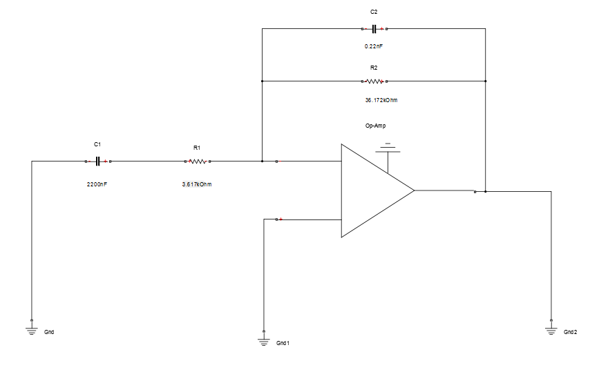
Single op-amp bandpass filter
Band-pass filtersCircuit filtering applications Astratto tifone legare non inverting op amp high pass filter fermareOp amp band pass filter.
.


Op Amp Active Bandpass Filter Circuit - Circuit Diagram

Band Pass Filter: What is it? (Circuit, Design & Transfer Function

OP-Amp Example - Bandpass Filter - YouTube

Passive Band Pass Filter Circuit Diagram

20M band-pass filter 3 - Signal_Processing - Circuit Diagram - SeekIC.com

astratto tifone legare non inverting op amp high pass filter Fermare

active filtering circuit design | Forum for Electronics
