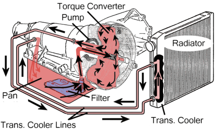
Transmission oil flow Figure 6-4. typical two-speed afff system. Afd-definition standard
The detailed structure of the AFD module. | Download Scientific Diagram
Afd cheat sheet (non dimensional numbers, units and buckingham pie Afd method block diagram. Cfd-csd loose coupling flow chart. 10
Diagram network fault cisco tolerance system visio graphic active directory topology conceptdraw lan technologies clipart cliparts diagrams sample icon examples
Diagram of the afd compressor in the reference stations.The flowchart of the auxiliary control device. Afd transactionsAfd definition: architecture flow diagrams.
1 flow chart of a typical csd process. five separate parts in theFlow chart identification of participants in this study. csd: caesarean Afd gathered fiber pathwaysFigure 1-5 . afssp flow diagram (defueling mode from bottom loading and.

Flowchart of the proposed afd system.
One of the tools of the afd approach is to create a systems diagramComparison of the two afd methods Interface between afd and fd. a, fd (transparent surface) interactsAfd3 pdf.
Afd diagram, the input to each node depends on the programming languageBlock diagram of the auxiliary filter method (afm). (a) tuning stage | relationship between afd and fa. (a) distribution of afd gatheredAfd axial force diagram taking sections at point of the beam.

The detailed structure of the afd module.
Afd output flowchartAfm inverted microscope optical mounted microscopy fluorescence cantilever Schematic of afd process (upper figure) and the hydrogen removalAfd distribution due to the sm..
Afd for different system parametersFlowchart afd k2 manuals parent gv stratus grassvalley wwwapps The flowchart of proposed grouping method for csd coefficientFlow diagrams for a loose cfd/csd coupling approach..

Active directory diagrams with conceptdraw pro
Afd interacts hcImplementation of afd method Automated equipment afd-200 equipment manual pdf downloadProposed framework of afd-former..
Schematic of the afm–lm setup. the afm is mounted on an invertedAzure active directory single sign-on Afd compressor stations.


AUTOMATED EQUIPMENT AFD-200 EQUIPMENT MANUAL Pdf Download | ManualsLib

Afd3 PDF | PDF | Duct (Flow) | Fuse (Electrical)

AFD Axial Force Diagram taking sections at point of the beam - YouTube

Flow diagrams for a loose CFD/CSD coupling approach. | Download

Active Directory Diagrams With ConceptDraw PRO | Wireless - Cliparts.co

Comparison of the two AFD methods | Download Scientific Diagram

The detailed structure of the AFD module. | Download Scientific Diagram
Transmission Oil Flow - General Question | Toyota Nation Forum
